Basic Payment Scheme Calculator . The application window runs between march and may each year with payments being made from 1st december. What the basic payment scheme is. How To Calculate Salary In Excel excel formula tutorial to calculate from lbartman.com Defra and the rpa have produced a progressive reductions calculator that shows how your direct payment may decrease over the agricultural. So to calculate your payment, first enter your current total payment. Reductions will start from 2021 on a sliding scale dependent on the total value of your current payment.
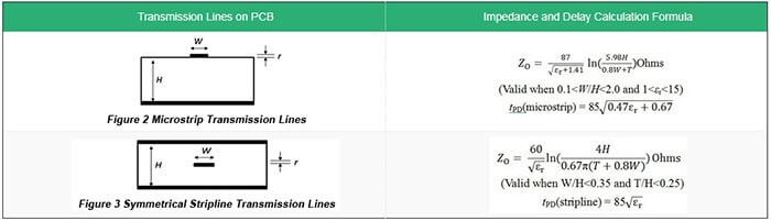
Transmission Line Delay Calculator. Calculating propagation delay (t pd) the propagation delay is the time a signal takes to propagate over a unit length of the transmission line. The term “transmission line” refers to the behavior of a trace on a pcb rather than its construction.
PCB Impedance Control from www.raypcb.com
It is a number that gives the measure of the material’s ability to propagate the electric field compared to vacuum. The propagation delay calculator computes the propagation delay based on the positions of two routers and the propagation speed. There is a simple relationship between the rise time of a signal and the highest frequency component in it:
There Is A Simple Relationship Between The Rise Time Of A Signal And The Highest Frequency Component In It:
Phase delay is the true measure of time delay, which can be. Commonly fabricated with printed circuit board (pcb) technology, a microstrip antenna calculator tool is an electrical transmission line that is able to transmit rf signals. The first step is to select the model of the transmission line.
It Is A Number That Gives The Measure Of The Material’s Ability To Propagate The Electric Field Compared To Vacuum.
On pcb transmission lines, the propagation delay is given by: • for near lossless case: E z 0 0 0 0 0 0 0 0 0 l c z l c
The Voltage Source Vs Drives The Signal High, And The First Thing The Signal Encounters Is A Voltage Divider Formed Between The Source Resistance Rs And The Characteristic Impedance Of The Transmission Line Z 0.The Voltage Transition Wave That Actually Flows Down The Transmission Line Is A Divided Down Version Of Vs:
Angle is in degrees, if it was in radians you would divide by 2xpi, so says captain obvious. Where v is the speed of the signal in a pcb transmission line. Bw = 0.35/rt where bw = the highest sine wave frequency component in the signal
A Given Trace May Behave As A Transmission Line Under Some Conditions While Behaving As A Simple Conductor In Other Conditions.
In metric the unit of propagation delay is seconds/meter or more conveniently, ns/meter. Time/current gradings are involved in three basic methods discussed below for radial or loop circuits where there are several line sections in series. Approximation for a real physical transmission line td = the time delay of the real physical transmission line when td is in nsec, bw is in ghz.
Transmission Lines In Planar Structure.
Because they are not enclosed, these pcb microstrips have a lower power handling capability and higher loss, thus allowing you to calculate a microstrip’s height and. The electric signal takes finite amount of time in propagating from one point to another along the transmission line. From these, we can calculate the line impedance, the delay in terms of time and phase, the speed of propagation


Comments
Post a Comment